




We have designed, and produced a prototype for, a bicycle-stabilizer attachment and we have developed a prototyping process for micro-mobility class vehicle-design.








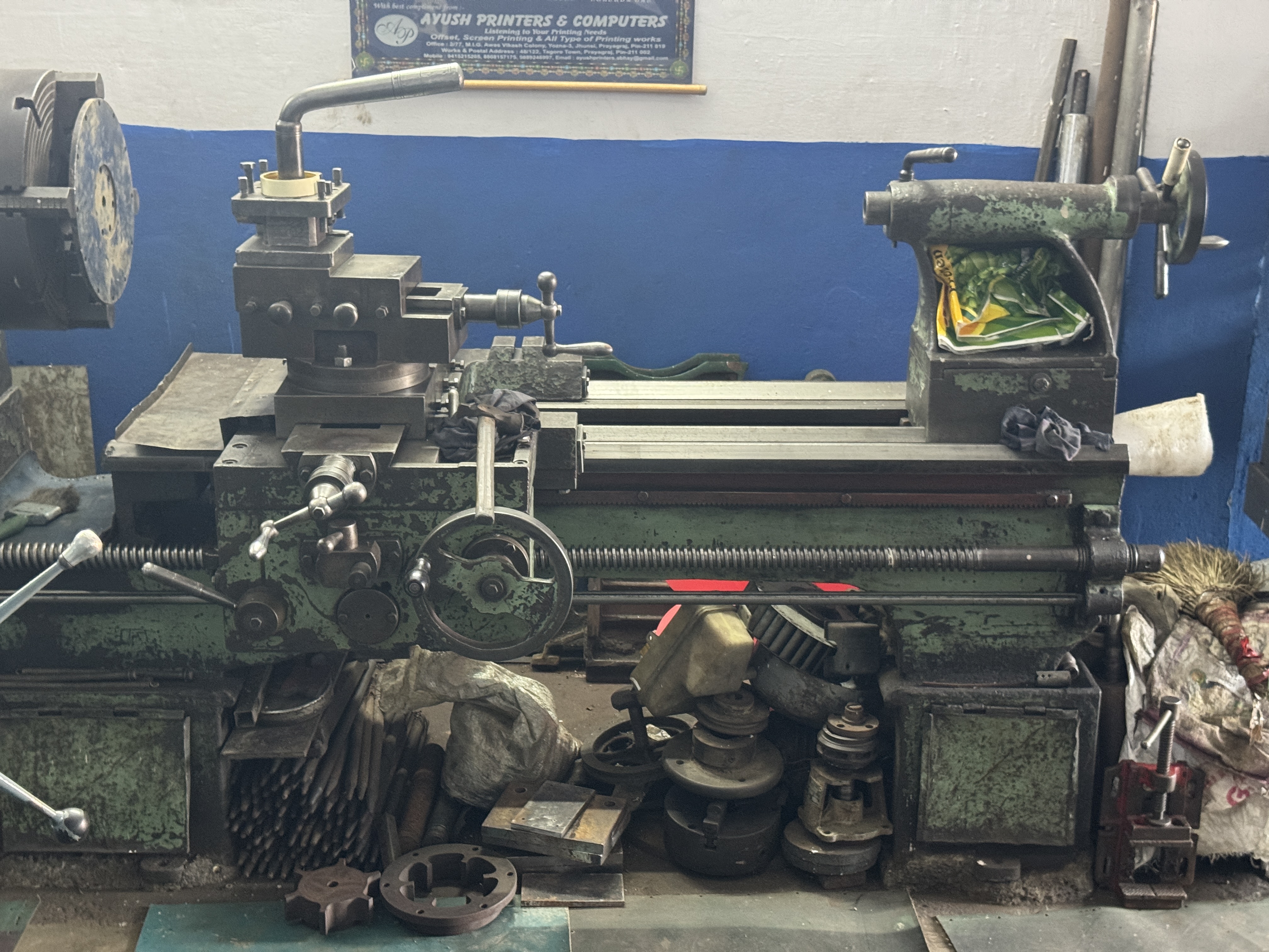
We developed a prototyping process by finding a skilled lathe operator. The lathe was part of a small micro-factory that provides metal machining services.
We started our prototyping by using the identified machining service and employing the services of nearby bicycle machanics. The first component produced was a 17 mm diameter silver-steel axle that was machined on the lathe on both sides with 1 mm threads to fit (16 mm x 1 mm) nuts.
In addition to the lathe, the facility included cutting, drilling and forging services. It was located in a densely populated area with high bicycle, tricycle and 3-wheeled lightweight DC-motor taxis in a addition to pedestrian traffic. Access to nuts and bolts, ball-bearing casings, sheet-metal, cross-sections etc., was all in the vicinity.
We sourced all materials locally, got parts constructed by the machining service, assembled the design with the help of nearby bicycle mechanics and tested it on local roads and made revisions.


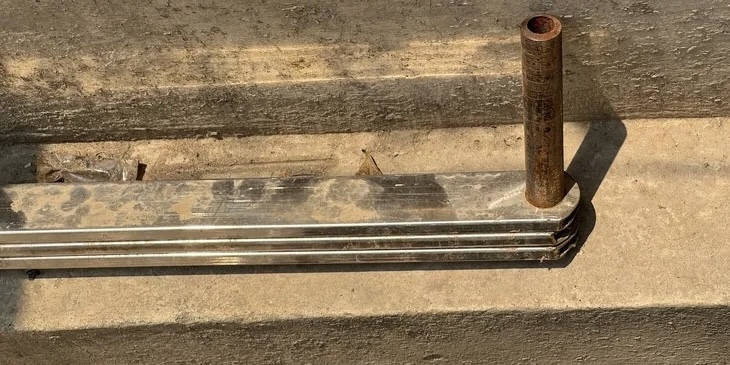
All structural elements (for pulling, steering, strengthening and frame-building) are made using rectangular cross-section (40mm x 8mm), hollow (2mm gauge) steel beams. Weight is about 1.6kg/m. These beams are strengthened at their attachment points with iron plate segments. A 4mm thick iron plate segment fits inside the beam and two 2mm thick plate segments sandwich it from the outside. The 3 plates and beam section are aligned, bored through with 2mm holes and riveted (this keeps weight low while providing strength where needed).

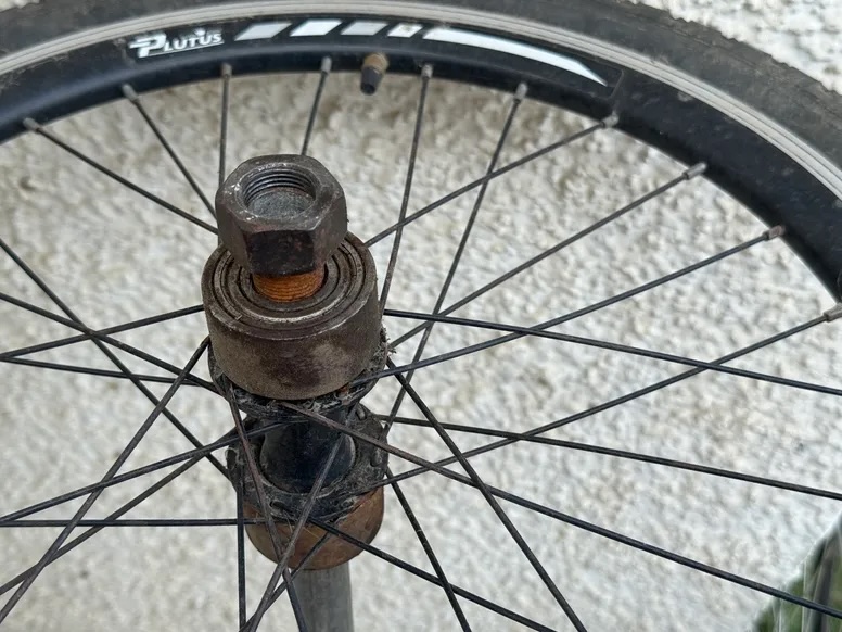
We take a stock bicycle wheel,
and remove the ball-bearing and inner ball-bearing holder attachments from the wheel-hub.
We add 1mm threads to both outer-extensions of the hub.
The OD of these extensions is about 35mm.
We use a 48.3mm OD seamless pipe (schedule 160) with a wall-thickness of 7.14mm (ID 34.02mm) to create sleeves.
We create a sleeve with an inner diameter of 35mm on one side.
We add 1mm threads to the inside of the sleeve on this side for 12mm.
This side of the sleeve is screwed into the outer-extension of the hub.
On the other side, it is bored depending on its usage.

We bore the outer side of the sleeve to a 40mm diameter with a 12mm depth. A 6203 bearing (40mm x 17mm x 12mm) slots into this bore. The 17mm axle fits inside this bearing. The total width of this sleeve is (12+12) 24mm. We also use a bearing between wheels for the wheel-pair. Since this bearing fits between wheels and we want to minimize spacing between the wheels in the pair, we only bore the sleeve to a 6mm depth on the bearing side (instead of 12mm). The bearing slots halfway into one wheel's sleeve and halfway into the other wheel's sleeve. These sleeves are therefore (12+6) 18mm wide. We remove 2mm of material from the outside of both these sleeves, for an OD of 44.3 mm. We create an addition sleeve (36mm wide) that is bored to 44.3mm. This sleeve serves to align the 2 wheel-hub sleeves and hence the wheel-pair.

The bearing used in this case is 6004 (20mm x 42mm x 12mm). A pair of single sided sleeves is created for each wheel in this case.

We have been protoytyping and testing modifications to existing land-vehicle designs since 2016. Below is a summary of some of this work.

We've done several small bicycle modifications, and then explored tricycle design. We've worked on muffler modifications for sound tuning and some structural, frame-related modifications on motorcycles.
We redesigned the seating and suspension system of a roadster bicycle, and also added a small carrier for groceries. The suspension used a combination of a leaf-spring and a pair of coil-springs.


We have analysed the design considerations for 3-wheeled transportation, through an observation of bare-bones, cost-optimised operational designs.

We have made a few interior modifications, and some weatherisation, aerodynamics and rigidity related modifications.

We redesigned the roof of an SUV to flow air through the car while keeping the rain out. We also studied possible approaches to weatherization in such a vehicle.

We plan to design a sub-compact 4-door hatchback that flows air through the car, features body-on-frame construction and a cabin-center driving position.